What Is an Industrial Water Pump and How Does It Work?
An industrial water pump is a mechanical system that moves water through pipes, filters, heat exchangers, tanks, and production equipment. It converts motor power into fluid movement. The pump creates a pressure difference, allowing water to travel from a lower-energy point to a higher-energy point. In simple terms, it gives water the force to move.
Typical equipment includes an electric motor, impeller, casing, shaft, seals, bearings, valves, and control sensors. A centrifugal pump spins its impeller and increases water velocity. The casing then changes much of that velocity into pressure. Positive displacement pumps work differently. They trap fixed volumes and push them forward. The choice depends on flow rate, pressure, temperature, viscosity, water quality, and operating duty. Small details matter. Sand can damage seals. Poor alignment can heat bearings.
The U.S. Department of Energy’s Improving Pumping System Performance: A Sourcebook for Industry reports that pumping systems may represent about 25% of industrial electricity consumption. The International Energy Agency also identifies motor-driven systems as a major global electricity user. These figures explain why pump efficiency deserves careful attention. A higher-rated motor alone does not guarantee lower operating costs. Oversized pumps often throttle flow and waste energy.
This guide explains how an industrial water pump works, where its energy goes, and how engineers evaluate performance. It is not a substitute for site testing. Real systems behave imperfectly. Flow changes. Equipment ages. Good decisions combine manufacturer data, field measurements, maintenance records, and professional judgment.
What Defines an Industrial Water Pump: Flow, Head, and 70–90% Efficiency
An industrial water pump moves water through factories, cooling systems, treatment plants, and irrigation networks. It uses an impeller, diaphragm, or piston to create pressure and maintain movement. The correct pump is defined mainly by flow and head, not by physical size alone. Flow measures the water delivered over time, usually in cubic meters per hour. Head describes the energy needed to lift water and overcome pipe resistance. A pump may deliver high flow but fail when the system requires greater head.
Efficiency shows how much input energy becomes useful water movement. Many well-selected industrial pumps operate between 70% and 90% efficiency. This range depends on pump design, operating speed, fluid condition, and system resistance. A pump running far from its best efficiency point can waste power, vibrate, and heat the bearings. Small losses become expensive over long operating hours.
That matters.
In field checks, technicians compare flow meters, pressure gauges, motor power, and operating temperature. A practical calculation uses hydraulic output against electrical input, although measurement errors can affect the result. Head can also change when filters become blocked or valves are partly closed. This is often overlooked. Selecting a pump at the upper limit may seem safe, but excessive capacity can create unstable control and unnecessary energy use. Regular inspection helps confirm whether the pump still matches real demand.
No calculation is perfect.
Core Pump Components: Motors, Impellers, Casings, Shafts, and Seals
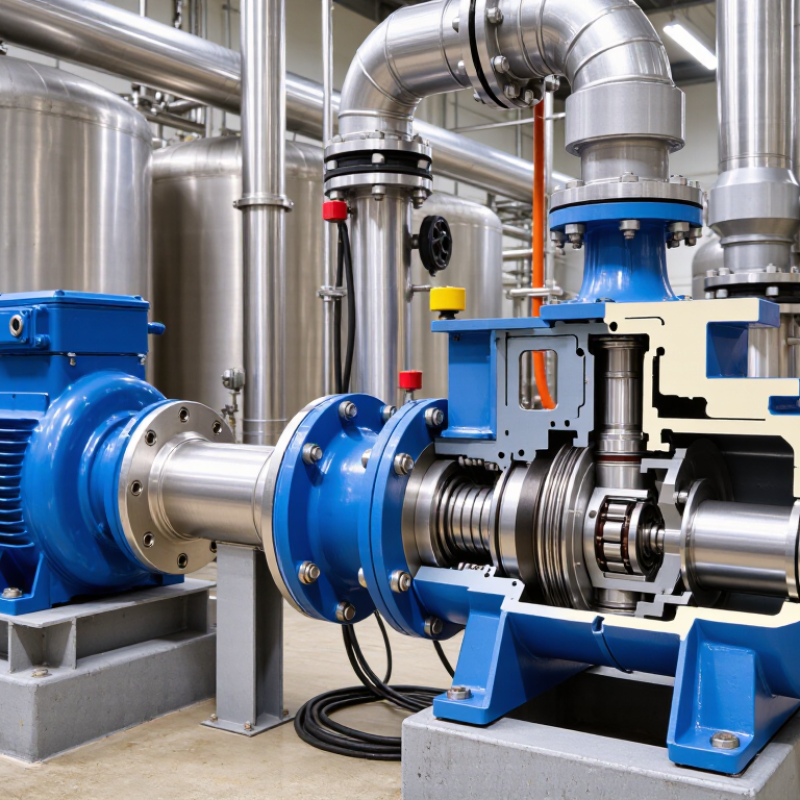
An industrial water pump converts mechanical energy into controlled water flow. The motor supplies rotational power, usually through an electric drive. Its speed affects flow, pressure, noise, and energy demand. The U.S. Department of Energy reports that pumping systems may consume 25–50% of an industrial facility’s electricity. Small efficiency losses can therefore become expensive.
Inside the casing, the impeller spins like a curved metal wheel. It accelerates water outward and raises its velocity. The casing then guides that water toward the discharge outlet. Its shape also converts part of the velocity into pressure. The shaft transfers torque from the motor to the impeller. It must remain aligned, because slight bending can cause vibration, bearing wear, and premature failure. This is often underestimated.
Seals prevent water from escaping along the rotating shaft. Mechanical seals use carefully pressed faces, while packing relies on controlled compression and leakage. Both require correct installation and suitable materials. A dry-running pump can damage its seal within minutes. The Hydraulic Institute emphasizes proper pump selection, system assessment, and maintenance for reliable performance. Yet operating data is not always complete. Flow meters may drift, and operators sometimes trust sound instead of measurements. That habit needs reconsideration. A worn impeller, blocked intake, or oversized motor may still appear functional while wasting energy. Inspect the casing, shaft, impeller, and seal together. Their interaction determines real pump performance.
What Is an Industrial Water Pump and How Does It Work?
A centrifugal industrial water pump uses a motor to rotate an impeller. The impeller transfers energy to the water, while the casing converts velocity into pressure. The shaft transmits torque, and mechanical seals help prevent leakage around the rotating shaft.
The chart shows a representative centrifugal pump performance curve. Efficiency generally increases toward the best-efficiency point, then declines when the pump operates far from its design flow. Actual results depend on impeller diameter, motor speed, fluid properties, casing design, shaft alignment, and seal condition.
Water Intake and NPSH: Preventing Cavitation at 1,450–3,600 rpm
An industrial water pump converts motor power into controlled water flow. Its impeller spins inside a casing, creating pressure that moves water through pipes. At 1,450–3,600 rpm, the intake design becomes critical. High speed can reduce pressure at the impeller eye, especially when the suction pipe is narrow, long, or partly blocked.
NPSH means Net Positive Suction Head. NPSH available must exceed the pump’s required value, with a practical safety margin. This margin protects against cavitation, where vapor bubbles form and collapse near the impeller. The damage may appear as gravel-like noise, unstable flow, vibration, or pitted metal. A clean intake screen, short suction line, gentle pipe bends, and sufficient water level all help. Avoid sharp suction throttling. It can create trouble quickly. In field inspections, operators sometimes trust pressure readings alone, but vibration and sound often reveal the problem earlier.
Tips:
Measure water temperature, static level, suction pressure, and flow during real operation. Compare NPSH available with the pump curve at the actual speed. Reduce speed when possible, but check the operating point carefully. More speed is not always better. A partially closed valve may seem harmless, yet it can starve the impeller. I have seen a clean pump blamed for cavitation when the real cause was a blocked intake screen. Check the intake first.
Pressure Generation: Converting Rotation into 10–100+ Metres of Head
An industrial water pump converts shaft rotation into pressure and flow. The central variable is head, measured in metres of water. Ten metres of head produces about 0.98 bar, while 100 metres produces nearly 9.8 bar at room temperature. The relationship is simple:
pressure equals density multiplied by gravity and head.
Real installations are messier.
A centrifugal pump accelerates water through a rotating impeller. The casing then slows the liquid and converts velocity into pressure. Pump speed, impeller diameter, friction, elevation, and valve resistance determine the final operating point. A 50-metre target does not guarantee 50 metres at the outlet. Pipe losses can consume a surprising share.
The U.S. Department of Energy’s Improving Pumping System Performance sourcebook reports that pumping systems may represent 25–50% of industrial electricity use in facilities where liquid movement is significant. That makes correct sizing an operating decision, not merely a purchasing detail.
Power demand rises with flow, head, and fluid density. Hydraulic power can be estimated as
P = ρgQH,
then adjusted for pump and motor efficiency. The Hydraulic Institute recommends evaluating pumps across their expected duty range, rather than relying on one catalogue point. Field measurements often expose the gap. A pressure gauge may reveal unstable suction, while a flow meter may show a system running far from its best efficiency point. The calculation is useful, but it is not perfect.
U.S. DOE, Improving Pumping System Performance: A Sourcebook; Hydraulic Institute, ANSI/HI pump standards.
Discharge and Control: Managing Flow, Energy Use, and ISO 5199 Testing
An industrial water pump converts mechanical energy into controlled liquid flow. Its discharge side determines whether that energy becomes useful pressure or avoidable loss. A pressure gauge near the outlet can reveal unstable operation, while a flow meter shows whether the system meets its process demand.
The U.S. Department of Energy reports that pumping systems may represent about 25% of industrial motor-system electricity use. This makes control strategy important. Throttling a valve can reduce flow, but it often wastes energy as pressure loss. A variable-speed drive usually offers better control when demand changes frequently. Lower speed also reduces hydraulic power sharply. The calculation is not always elegant. Actual pipe fouling, air pockets, and worn impellers can distort expected results.
ISO 5199 provides technical requirements for centrifugal pump design, construction, inspection, and documentation. Hydraulic performance acceptance is commonly assessed with ISO 9906 procedures, including head, flow, and efficiency measurements. Operators should record discharge pressure, vibration, temperature, and motor power during testing. These readings connect workshop results with field performance. A pump passing a factory test may still perform poorly after installation. Alignment, suction conditions, and control settings matter. DOE pumping-system guidance also recommends comparing measured duty points with system requirements before resizing equipment. That practical check can prevent oversized pumps, excessive energy use, and unstable discharge control.