

Our Blog
Check out our innovative pump solutions and industry insights to see what's new in the pumping industry. Stay up to date with the latest trends and news in the world of pumping technology by following our pumping technology blog.
- Home
- Blog
How to Choose a Telecentric Zoom Lens for Machine Vision?
Machine vision is moving from isolated inspection cells into faster, more connected production systems. MarketsandMarkets’ Machine Vision Market report projects growth from approximately USD 12.8 billion in 2023 to USD 17.2 billion by 2028. This expansion increases pressure on engineers to select optics carefully, not merely quickly. A Telecentric Zoom Lens can preserve image scale while accommodating different inspection distances. That matters when a camera measures connector pins, molded edges, or small stamped holes. The wrong lens may create distorted dimensions, soft corners, or unstable measurement results.
Choosing the lens requires more than checking magnification. Engineers should compare telecentricity, zoom range, sensor coverage, working distance, depth of field, numerical aperture, and lighting compatibility. The EMVA 1288 standard provides a reliable framework for evaluating image quality, including resolution, noise, and sensitivity. These measurements are more useful than attractive sample images. A3 industry reports also continue to show strong demand for automated inspection across manufacturing, where repeatability remains central. In practical trials, place a calibrated target at the nearest and farthest inspection positions. Check whether critical edges remain sharp and whether measurements stay consistent. Small differences become costly at production speed. No lens is perfect. Even a premium Telecentric Zoom Lens may require better lighting, a rigid mount, or revised working distance. This is where selection becomes a technical decision, not a catalog comparison. The following guide examines those trade-offs and highlights where specifications may not match real factory conditions.
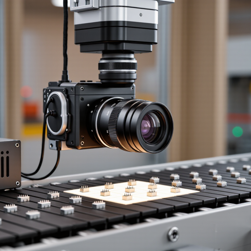
Define Telecentric Zoom Lens Principles and Key Terminology
A telecentric zoom lens is not simply a zoom lens with less distortion. Its defining principle is controlled ray geometry. In an object-space telecentric design, chief rays remain nearly parallel to the optical axis. Objects can move slightly without changing their measured size. This supports stable inspection of holes, edges, pins, and molded parts.
Key terminology matters. Working distance describes the space between the lens and target. Magnification determines how much of the object reaches the sensor. Telecentricity error indicates measurement variation caused by object movement. Depth of field defines the acceptable focus range. A bi-telecentric lens controls rays on both object and image sides, but usually costs more and requires tighter alignment.
Short sentences matter. Small errors grow.
The zoom function introduces a practical compromise. Telecentricity must remain consistent across every focal position, not only at one setting. According to the 2024 MarketsandMarkets Machine Vision Market report, the sector is projected to grow from about USD 11.6 billion in 2024 to USD 17.2 billion by 2029. This expansion increases demand for repeatable optical measurement. A 2024 Grand View Research report also identifies inspection automation as a major machine vision application area. I would not choose from magnification alone. Check sensor size, field of view, working distance, aperture, lighting clearance, and telecentricity error at both zoom limits. In practice, the published value may not match your production setup. Test a calibrated target at the real distance.
Match Lens Telecentricity to the Machine Vision Application
Choosing a telecentric zoom lens starts with the application, not the lens catalogue. Match lens telecentricity to the measurement task. In production, object-space telecentricity helps keep part dimensions stable when height changes slightly. This matters when inspecting machined edges, holes, or molded components. Image-space telecentricity can support consistent image scaling at the sensor. However, it does not solve every perspective problem. Keep this distinction clear.
Set the working distance around the actual fixture, not an ideal drawing. A zoom lens must maintain acceptable telecentricity across its full zoom range. Measure the field of view at the shortest and longest settings. Check distortion near the image corners. I prefer using a calibrated grid and a real sample part. Laboratory charts can hide practical problems. Small height shifts may still change edge contrast.
Sensor size, pixel pitch, aperture, and lighting also affect the choice. A lens may resolve fine marks but lose contrast at a narrow aperture. Another may offer useful depth of field but reduce brightness. Test both extremes. Record magnification, working distance, and measurement error for each setting. This creates evidence for repeatable decisions. I have learned that “telecentric” alone is not enough. Mounting stiffness, vibration, and imperfect alignment can weaken reliable results. Leave adjustment space in the mechanical design. The best compromise is sometimes less optical perfection and more stable operation.
| Machine Vision Application | Primary Inspection Goal | Recommended Telecentric Configuration | Typical Magnification Range | Typical Telecentricity Error | Recommended Working Distance | Key Selection Considerations |
|---|---|---|---|---|---|---|
| Precision dimensional measurement | Outer diameter, hole diameter, edge position, thickness, and distance measurement | Object-side telecentric; bi-telecentric when magnification stability is critical | Approximately 0.5×–2.0× | Preferably within ±0.1% of image-space scale for demanding measurement systems | Typically 100–200 mm | Match the lens resolution to the pixel size and tolerance; use controlled coaxial or diffuse lighting to reduce edge uncertainty. |
| Electronic component inspection | Lead spacing, connector dimensions, solder-joint position, and component placement | Object-side telecentric; zoom capability is useful when board formats vary | Approximately 0.3×–1.0× | Common target: ±0.1%–±0.2%, depending on tolerance and field size | Typically 80–150 mm | Check sensor coverage, chief-ray angle compatibility, and illumination clearance around tall components. |
| Semiconductor and wafer inspection | Fine pattern inspection, die dimensions, alignment marks, and surface defects | High-resolution object-side telecentric or bi-telecentric design | Approximately 0.5×–2.0× | Often targeted below ±0.1% for stable dimensional comparison | Typically 50–150 mm | Prioritize low distortion, high modulation transfer performance, low flare, and compatibility with monochromatic or narrow-band lighting. |
| Automotive parts inspection | Gasket profile, machined features, clips, fasteners, and molded-part dimensions | Object-side telecentric zoom lens; choose a larger field of view when parts vary in size | Approximately 0.1×–0.5× | Typically ±0.2% or better for general dimensional inspection | Typically 100–250 mm | Consider depth of field, vibration tolerance, long-distance lighting, and a mechanically fixed zoom position after setup. |
| Plastic molding and extrusion inspection | Flash, deformation, wall thickness, profile, and surface defects | Object-side telecentric with extended depth of field; bi-telecentric for high-accuracy profiles | Approximately 0.1×–0.7× | Usually ±0.2%–±0.5%, depending on part geometry and tolerance | Typically 100–300 mm | Balance aperture and depth of field; use diffuse or dome illumination to minimize highlights on glossy surfaces. |
| Pharmaceutical packaging inspection | Cap position, label alignment, blister geometry, fill level, and seal integrity | Object-side telecentric zoom lens for repeatable scale across package height variations | Approximately 0.1×–0.5× | Typically ±0.2%–±0.5% for dimensional checks | Typically 100–250 mm | Select a sealed or cleanable mechanical design where required; verify working distance and lighting access before installation. |
| Web, film, and sheet inspection | Width, edge position, coating defects, holes, scratches, and pattern registration | Object-side telecentric when dimensional accuracy is important; line-scan optics may be preferable for continuous webs | Approximately 0.05×–0.3× | Typically ±0.2%–±0.5% for dimensional monitoring | Typically 150–400 mm | Check field width, distortion across the full sensor, motion blur, and uniform illumination over the inspection area. |
| General presence and absence inspection | Part presence, orientation, assembly completeness, and gross feature detection | Low- to medium-telecentric object-side lens; standard machine-vision lens may be sufficient if scale variation is acceptable | Approximately 0.05×–0.3× | Often ±0.5% or application-dependent | Typically 100–300 mm | Do not over-specify telecentricity when measurement is not required; prioritize field of view, depth of field, cost, and installation space. |
Select Zoom Range, Working Distance, and Field of View
How to Choose a Telecentric Zoom Lens for Machine Vision?
Choosing a telecentric zoom lens begins with the required field of view, not the largest zoom ratio. The lens must capture the complete part while preserving dimensional accuracy. According to MarketsandMarkets’ 2024 Machine Vision Market report, the sector may grow from 13.1 billion dollars in 2023 to 19.9 billion dollars by 2028. That growth increases pressure for flexible inspection systems.
Set the working distance before selecting magnification. Measure from the lens reference plane to the nearest practical surface of the object. Then calculate field of view from sensor dimensions and optical magnification.
For example, a 12 millimeter sensor width and 0.2× magnification produce approximately 60 millimeters of horizontal coverage. Add clearance for lighting, conveyors, and part movement. Too little clearance creates mechanical problems. Too much distance may reduce available resolution.
Select a zoom range that covers real product variation, not every possible future project. A narrow range often improves optical consistency and simplifies calibration.
The EMVA 1288 standard recommends evaluating resolution, distortion, shading, and signal quality under defined conditions. Use those measurements when comparing lens performance.
A practical test should include the smallest feature, the darkest surface, and the most reflective part. Measure twice. Real assemblies rarely match drawings perfectly. This is where lens selection becomes less elegant, but more reliable.
Evaluate Resolution, Distortion, Aperture, and Sensor Compatibility
How to Choose a Telecentric Zoom Lens for Machine Vision?
Choosing a telecentric zoom lens requires more than matching focal length. In practical machine vision tests, resolution should preserve the smallest feature on the part. Compare the lens resolving power with the sensor’s pixel size. A sharp center is not enough. Check the corners too. Use a calibrated target at the actual working distance. If edge details blur, measurement reliability drops quickly.
Distortion can shift edges and create inaccurate dimensional results. For inspection tasks, select a lens with low and consistent distortion across its zoom range. Test several zoom positions, because performance may change. Aperture also affects image quality. A wide aperture admits more light but reduces depth of field. A smaller aperture can improve detail until diffraction appears. This tradeoff is easy to overlook. Sensor compatibility matters as well. Confirm the image circle, sensor format, pixel pitch, and available working distance. The sensor should not crop useful information. It matters.
Tips: Test the lens with production lighting, not showroom illumination. Record resolution, distortion, and exposure at each zoom setting. Leave adjustment margin for vibration and temperature changes. Reflective surfaces may behave differently from matte samples. One fixture cannot represent every part. I often prefer slightly lower magnification with stable focus, but this choice is not universal.
Verify Lighting, Calibration, Mounting, and System Integration
How to Choose a Telecentric Zoom Lens for Machine Vision?
Verify the lighting before judging the lens. Telecentric optics perform best when illumination is stable, even, and matched to the inspection surface. A ring light may reveal edges, while backlighting can produce a cleaner silhouette. Test the setup with real parts, not only a printed target. Shiny metal often creates reflections that appear to be lens distortion. They may not be.
Calibration should cover the entire zoom range and working distance. Use a certified grid or dimensional artifact with known measurements. Record pixel size, distortion, and repeatability at each setting. A lens can remain sharp while measurement accuracy changes slightly. Recheck calibration after focus adjustments, temperature changes, or mechanical movement. I have found that small mounting shifts can invalidate careful measurements.
Tips: Lock the zoom and focus rings after validation. Support heavy cameras separately. Keep cables away from moving stages. Confirm the sensor size, flange distance, and available mounting space before purchase. Then test communication with the controller, trigger system, lighting, and inspection software. Integration failures are often overlooked. A lens may meet its optical specification but still slow the production cycle. Leave room for adjustment, because real factory conditions are rarely as clean as the laboratory.